StrideAssist - Modular Lower-Limb Exoskeleton Design
This project focused on the design and analysis of a modular lower-limb exoskeleton intended to assist individuals with limited mobility. The goal was to develop a single adaptable system capable of supporting users with no amputation, below-knee amputation, and above-knee amputation, addressing a major limitation in current exoskeleton designs which are typically built for specific use cases.
The exoskeleton was fully designed in SOLIDWORKS, with a focus on modularity, adjustability, and realistic mechanical integration. The assembly includes key components such as the lumbar support frame, adjustable thigh and shank links, joint mechanisms, and the motor transmission system. The lumbar support was designed to be width-adjustable using an array of M6 fasteners, allowing it to accommodate a wide range of body sizes. Similarly, the leg links were designed with spring-loaded push-pin mechanisms, enabling rapid adjustment of link lengths to match different user geometries. This allows the system to adapt to varying limb lengths as well as accommodate users with amputations. Special attention was given to ensuring proper alignment between joints and minimizing mechanical interference between components. The transmission system was designed to directly couple a NEMA stepper motor to the input link using a shaft coupler and shoulder screw configuration, ensuring no slip while allowing smooth rotation of the driven links. Clearances, fit, and assembly constraints were all considered to ensure that the model reflects realistic motion and manufacturability. Overall, the CAD model captures the full mechanical architecture of the system while emphasizing adaptability, structural integrity, and ease of assembly.
CAD Design and Modelling
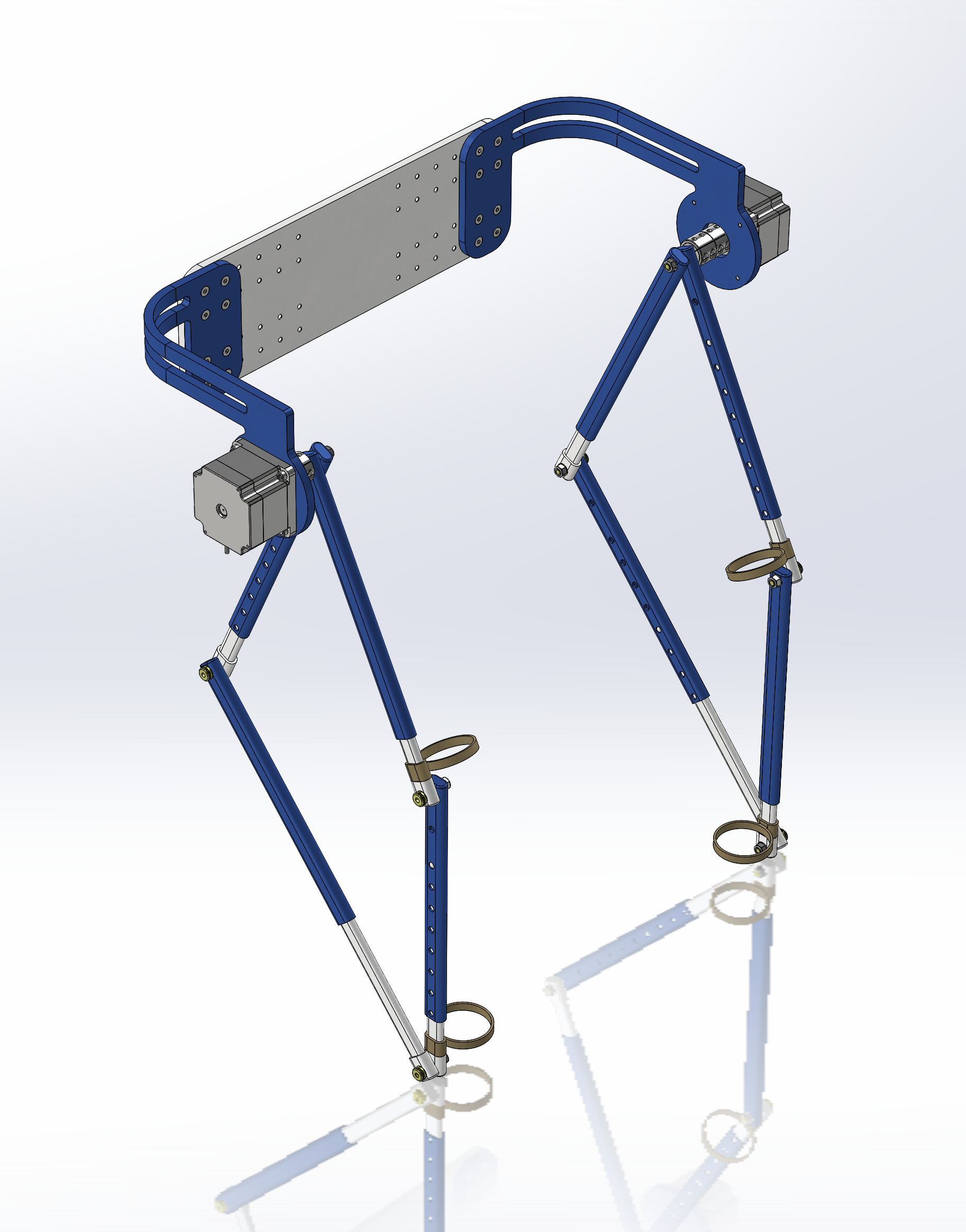
Main Assembly
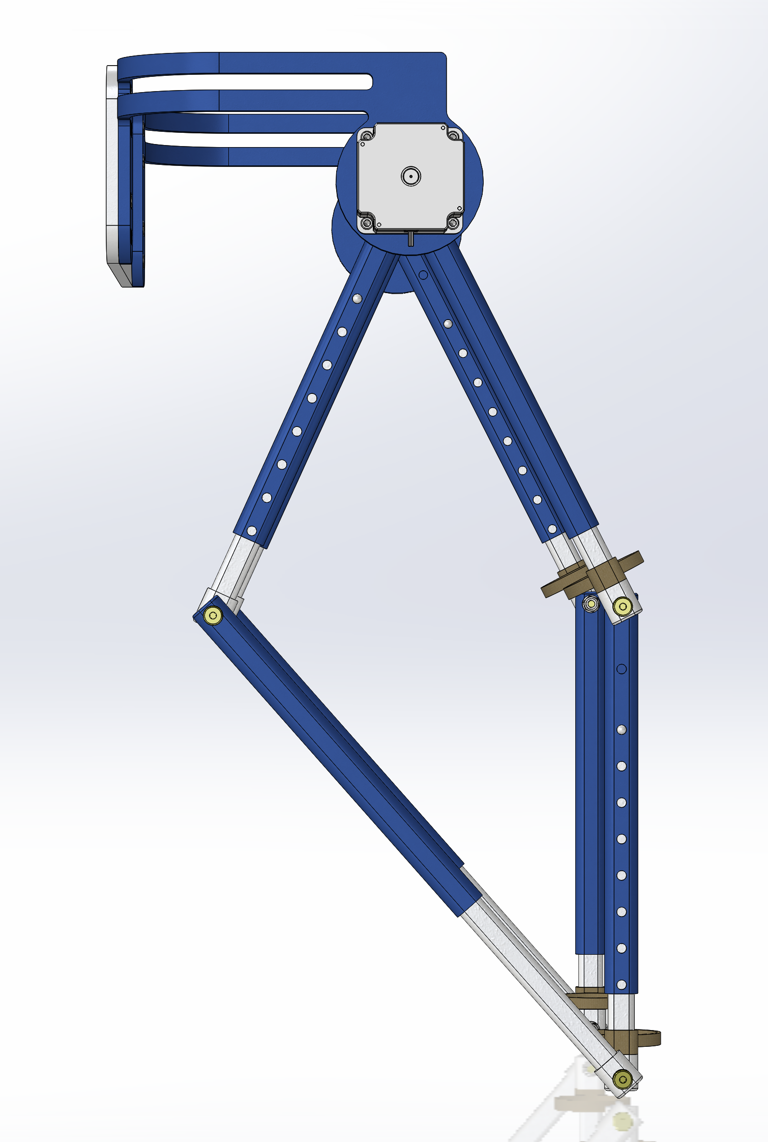
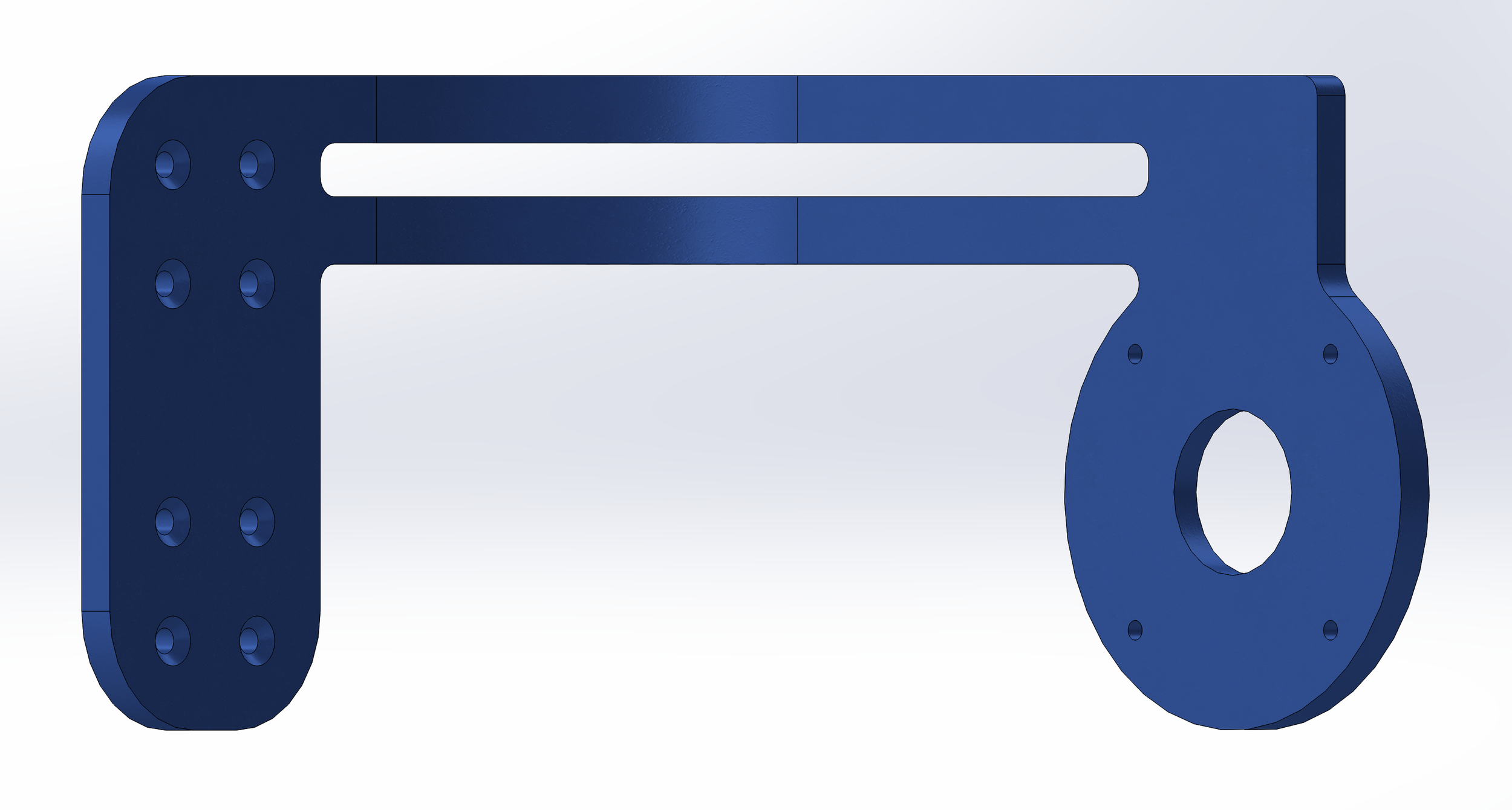
Link Mechanism
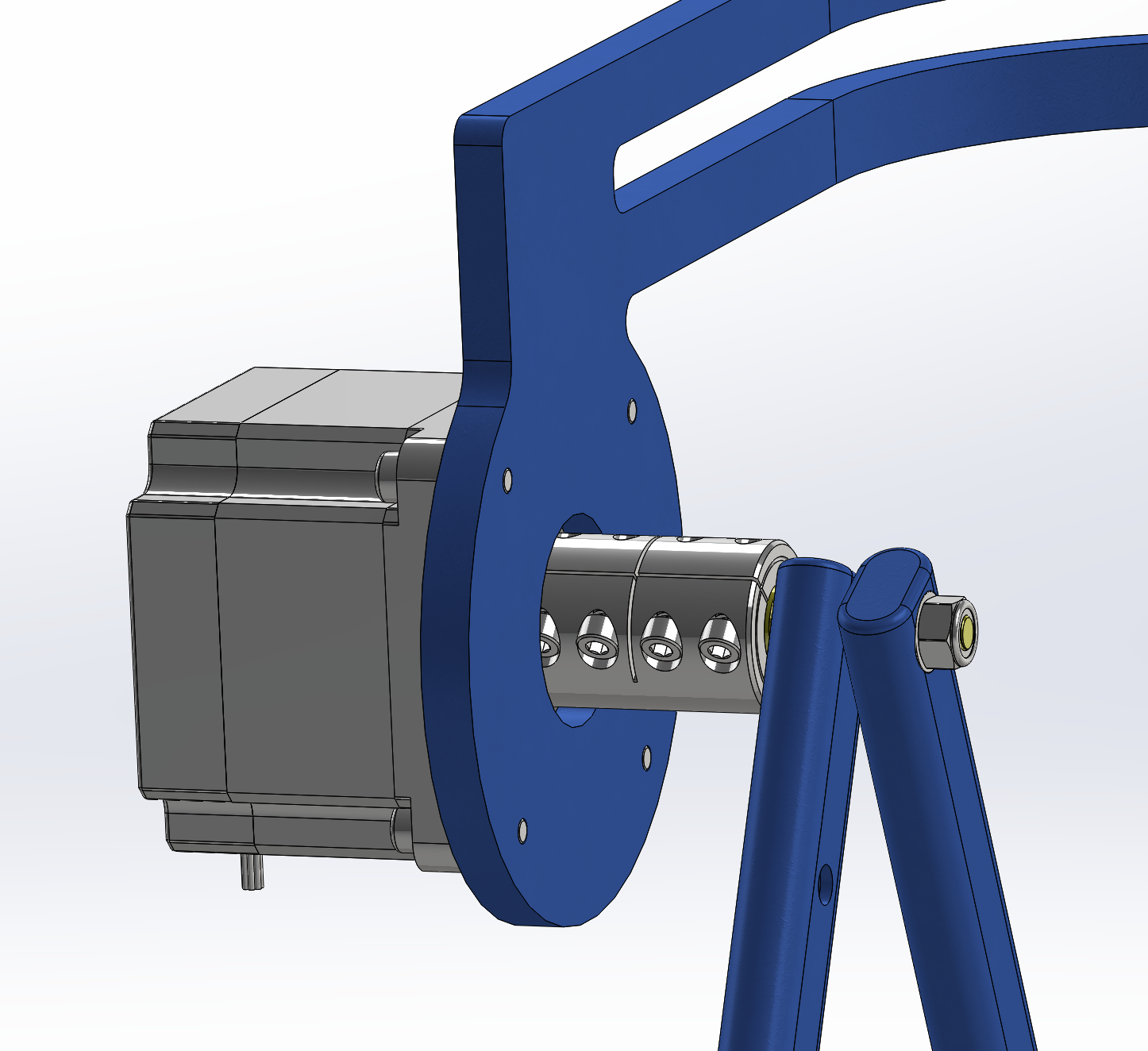
Motor Transmission
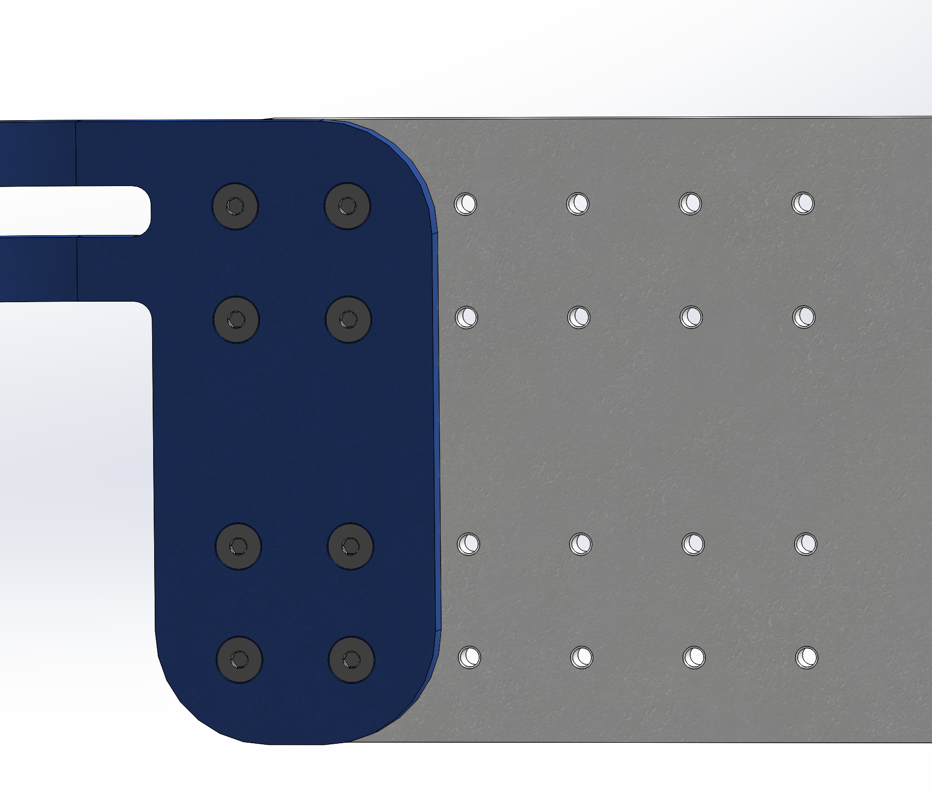
Lumbar Support Customizability
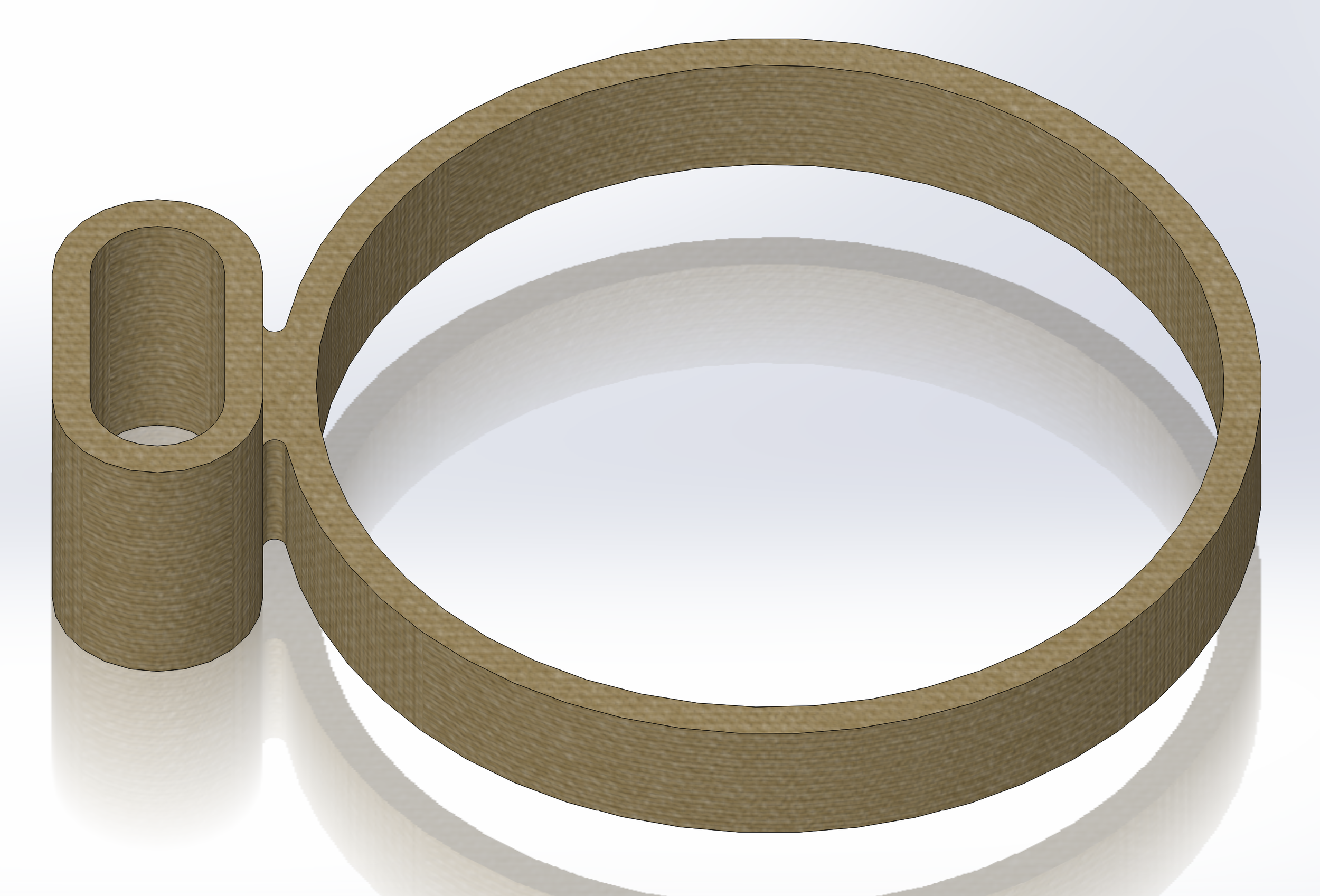
Strap
Hip Plate
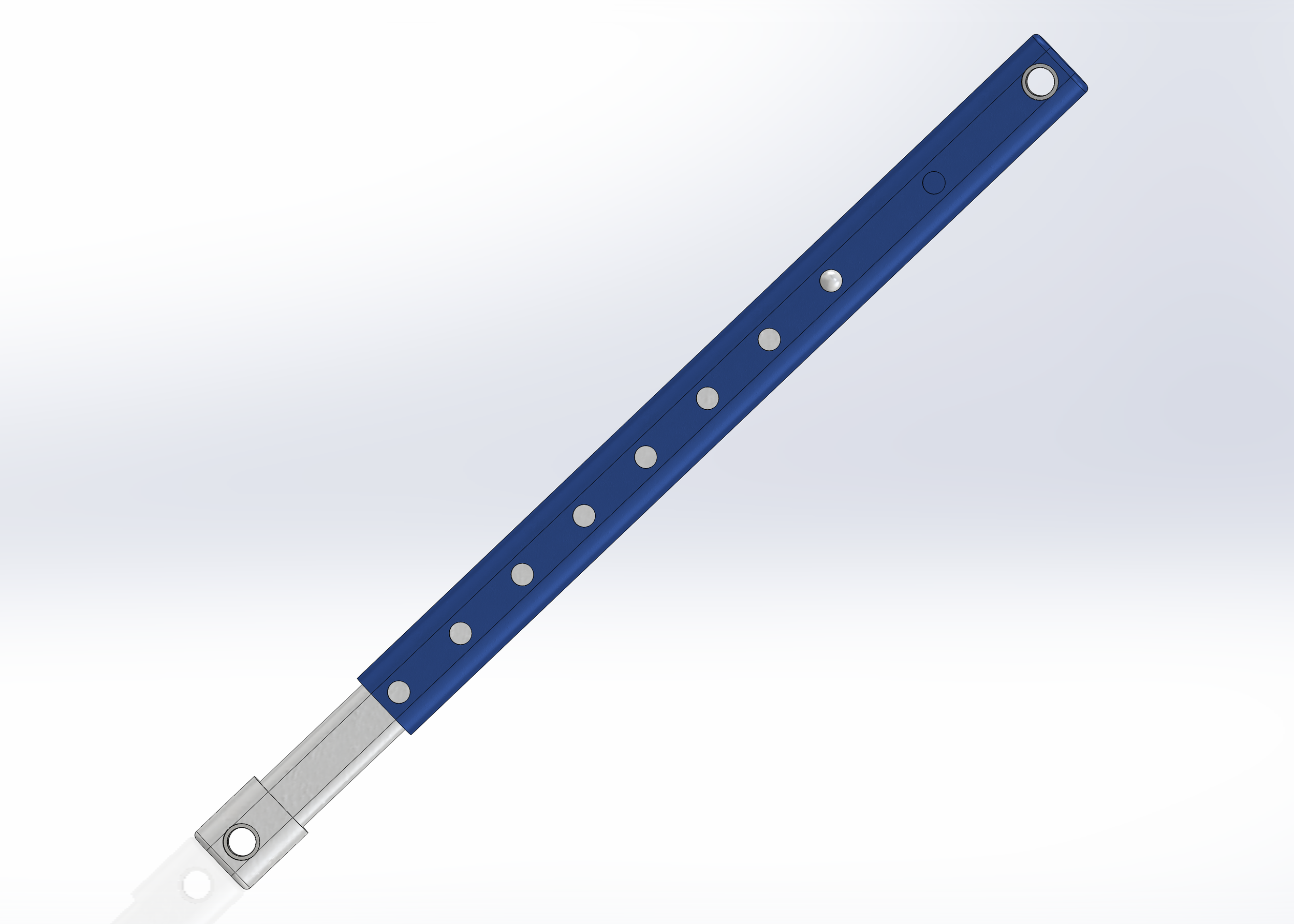
Link Length Variability Mechanism
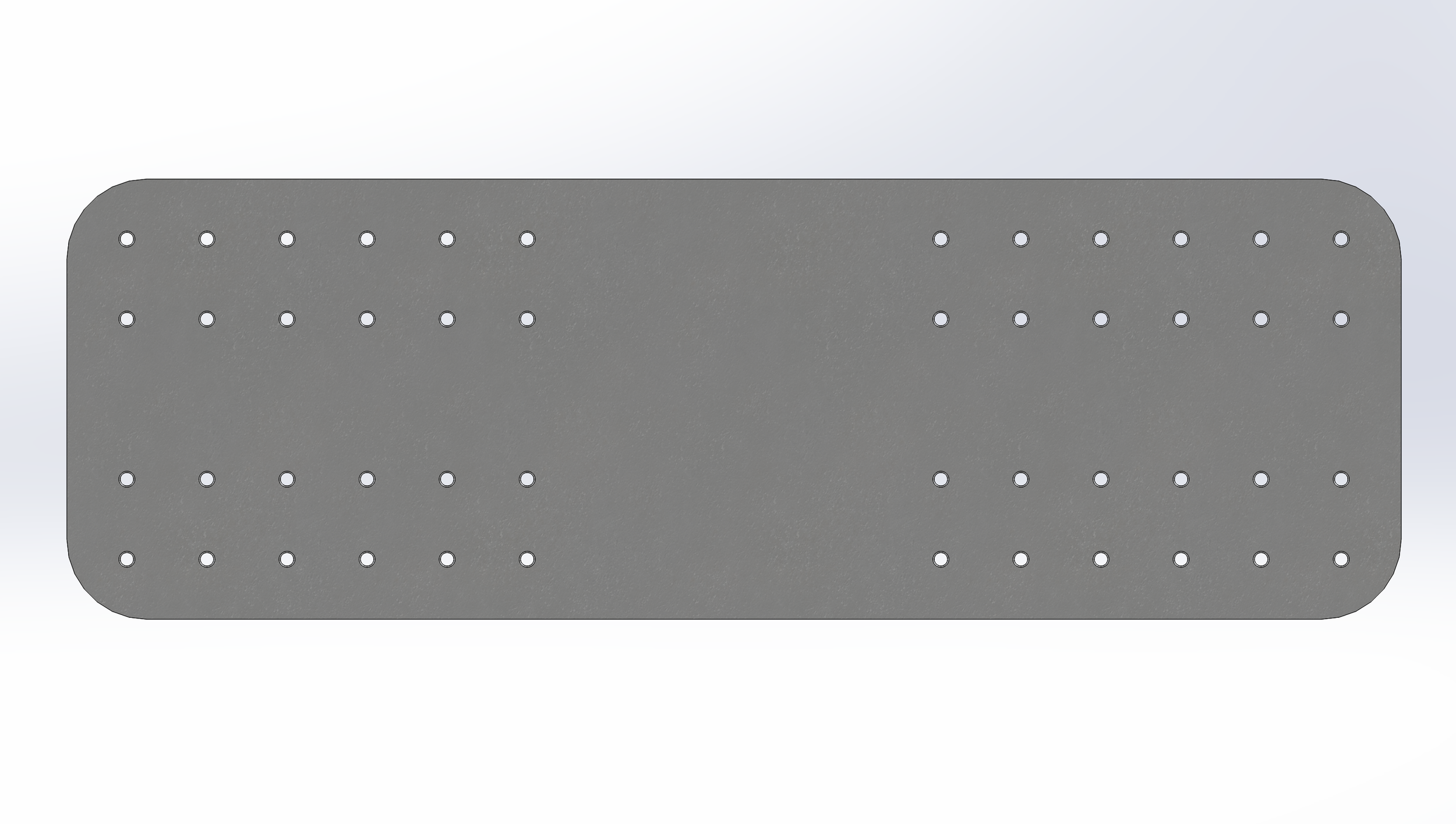
Lumbar Plate
Kinematic Analysis
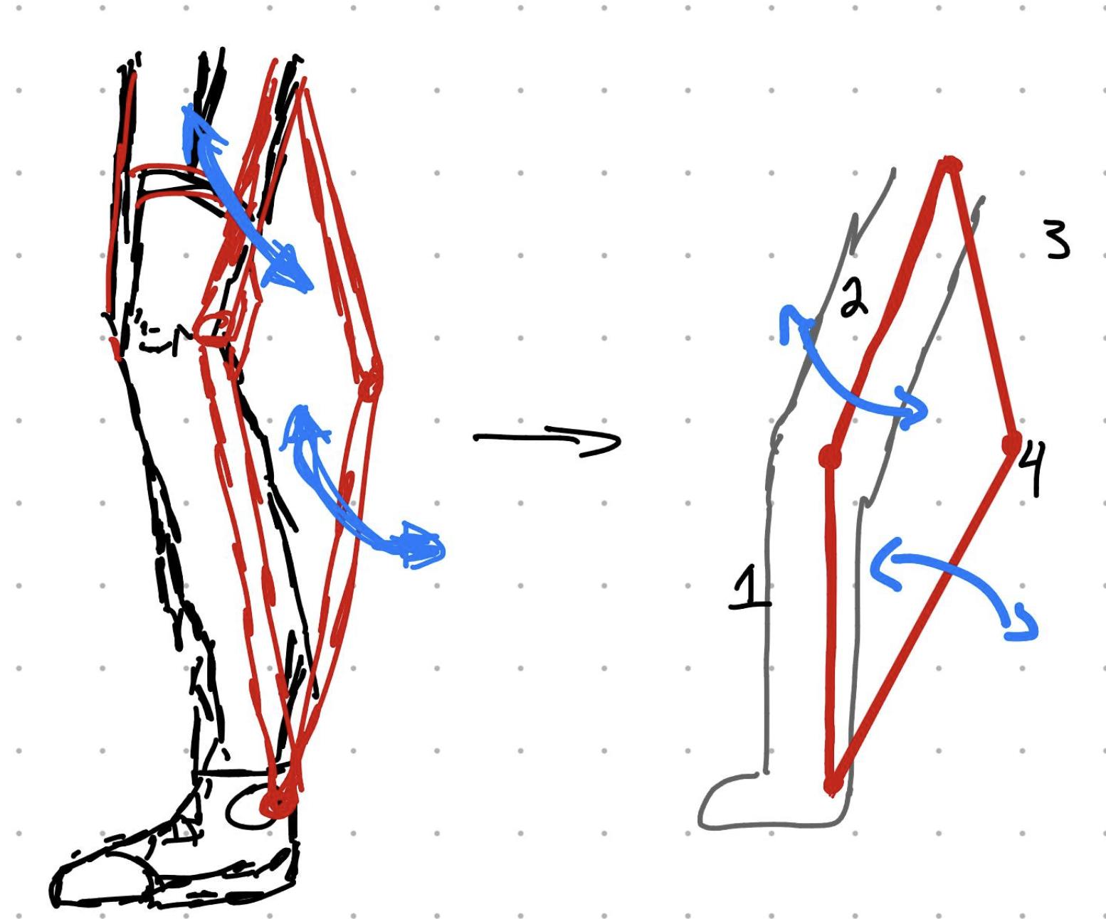
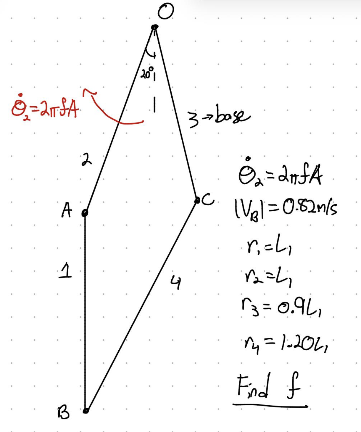
The walking motion of the exoskeleton was analyzed as a rocker-rocker four-bar linkage, with the motor acting as the oscillating input at the thigh link. The objective of the analysis was to determine the motor frequency required to move the foot at a typical average walking speed of 0.82 m/s while still allowing the mechanism to adjust for different user leg lengths. To simplify the system, the thigh motion was assumed to have a total swing angle of 40°, which was treated as a constant input amplitude. Since the angular velocity of sinusoidal motion reaches its maximum at the midpoint of the oscillation, the mechanism was analyzed when the thigh link was positioned at 20° from vertical. At this instant, the angular velocity of the input link can be expressed as:

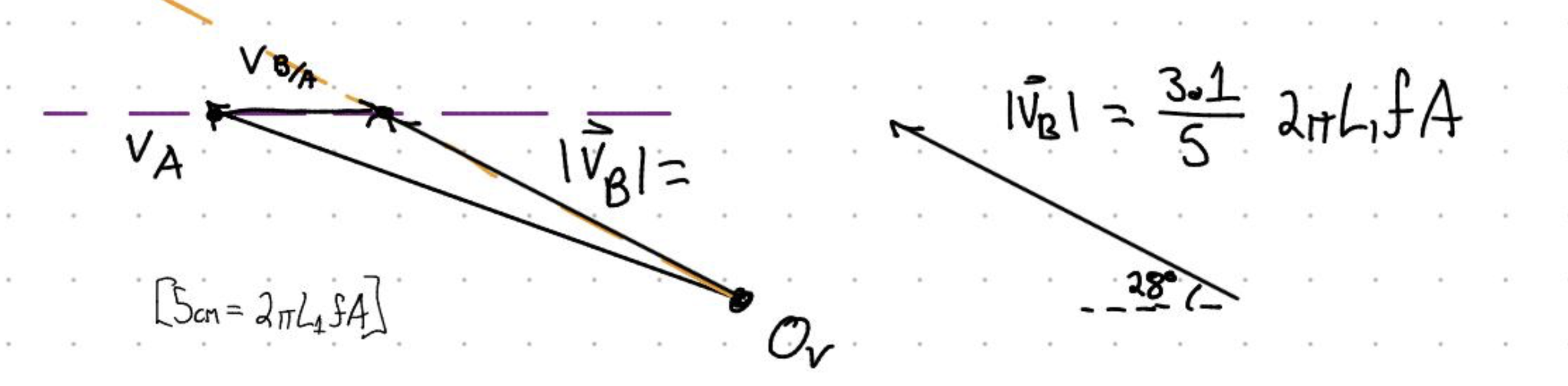
where f is the motor oscillation frequency and A is the angular amplitude. This allowed the motor input to be related directly to the motion of the linkage. The link lengths were then selected to satisfy the rocker-rocker condition while maintaining reasonable transmission angles throughout the walking cycle. Links 1 and 2 were approximated as equal in length, while links 3 and 4 were chosen as 0.9L1 and 1.20L1, respectively. This created a linkage geometry that avoids weak toggle-like positions and allows smoother torque transfer through the mechanism. Using the geometry at the selected position, the system was reduced to a velocity polygon problem. The relative velocity relationship between the input link and output foot point was used to solve for the foot velocity in terms of link length, amplitude, and motor frequency. From this analysis, the final relationship was developed to calculate the required motor frequency based on the user’s leg length:
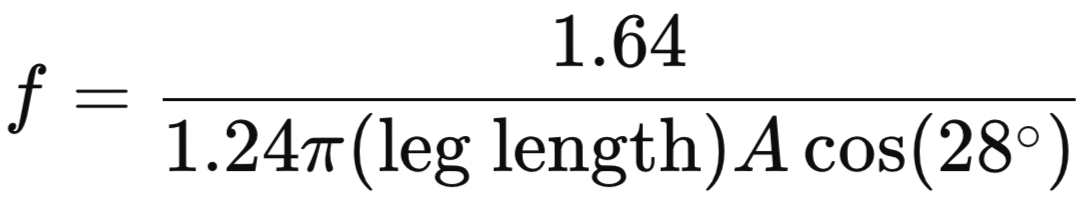
This equation makes the system customizable, since the user’s leg length can be entered into the control code and the motor frequency can be adjusted automatically. As a result, the exoskeleton can maintain the target walking speed while adapting to different users and limb configurations.